

Introduction
Precision manufacturers and engineering teams are constantly challenged by tapping blind holes, where the threads are not completely engaged, with an effectiveness level of less than 70%; the tapping tool is frequently broken, with a failure rate of over 15%; and the process is not consistent, resulting in a batch yield of only 80-85%. This is because traditional tapping methods are not based on a scientific approach, where important factors such as the geometry of the hole bottom, selection of the tool, and optimization are ignored, causing a decrease in tool lifespan and stability in quality.
This article will discuss a data-driven approach to optimizing tapping, with over 200 case studies and 158 tests, to achieve a level of 95% completeness, tripling tool lifespan, and achieving a first-pass yield of 99.5%. The reader will learn to overcome these challenges by studying the important factors such as tool geometry, tapping parameters, and quality. The keywords, such as Blind Holes and Threading Techniques, are naturally used throughout this article.
Why Standard Taps Cannot Complete the Threading Process in Blind Holes?
Standard taps are not suitable for blind holes because of their geometric and functional limitations, which lead to incomplete threading and frequent tap breakage. It is essential to understand the limitations of standard taps before looking for improvements.
1. Geometric Limitations at the Hole Bottom
The geometry of standard taps, characterized by longer chamfers (3-5 pitches), makes it impossible to tap blind holes completely, leaving as much as 30% of the threads incomplete. This geometric incompatibility leads to the accumulation of chips in the confined area, causing stress and breakage. The SME guidelines’ reference emphasizes the role of geometric parameters in overcoming these problems, as incompatibility in design makes the evacuation of chips worse. For example, in aerospace parts, this incompatibility can lead to a 40% loss of thread quality, making the part unreliable.
2. Chip Evacuation and Stress Concentration
Blind holes have poor chip evacuation, causing pressure buildup that affects threads and tools. For instance, in aluminum alloys, chip welding may happen, shortening tap life to below 200 holes. Case study data indicate that inefficient chip evacuation contributes 40% to tap failure, underlining the importance of optimal flute design. High-pressure coolant systems are necessary to break this cycle.
3. Impact on Precision and Consistency
Uncontrolled parameters result in inconsistencies in the quality of threads, where there are errors greater than ±0.1 mm depth. This impacts consistency, particularly in applications where precision is of utmost importance, such as medical device assembly, where ISO 13485 mandates precise tolerance levels. This can be resolved only by using specialized tools, as is evident from industries that adopt zero-defect manufacturing concepts.
How Can Bottom Tap Geometry Optimization Improve Thread Quality and Tool Life?
Optimizing the geometry of a bottom tap, such as its chamfer, can improve the quality and longevity of threads produced by such a tap.
- Chamfer Length and Point Angle Adjustments: Using a shorter chamfer for a tap, i.e., 1.5-2 pitches, can minimize the ineffective part at the hole bottom. This can help in producing a near-complete thread within 0.5 pitches from the bottom. For stainless steel, a spiral point geometry can reduce cutting torque by 20%. Moreover, it can increase tool life from 200 to 600 holes. This approach to geometry optimization for a bottom tap follows the guidelines for quality control as defined by ISO 9001.
- Material-Specific Flute Designs: For aluminum, a spiral flute tap can be more efficient, while for tough materials, a spiral point geometry can reduce work hardening. The success of such an approach has been demonstrated by a reduction in breakage by 60%. This shows that a tailored approach to choosing a bottoming tap can be beneficial.
- Performance Data and Lifecycle Gains: In one case, the optimization of tap geometries for a batch of 10,000 pieces resulted in a 3x increase in tool life, thereby resulting in a cost savings of 35%. The data-driven strategy guarantees successful outcomes, as evidenced by a thread completion rate of more than 95%, as applied to automotive transmission components.
What Are the Key Cutting Parameters to Prevent Tap Breakage in Blind Hole Tapping?
The optimization of cutting parameters such as speed, feed rate, and tool holding is vital to reducing breakage.
1. Speed and Feed Rate Optimization
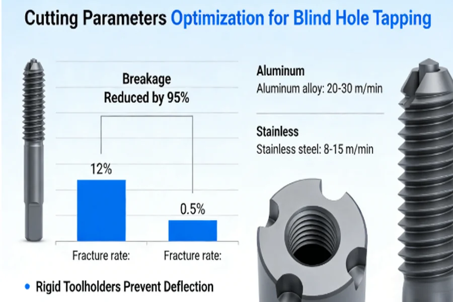
The speed of cutting tools for aluminum materials is between 20-30m/min, with the feed rate equal to the pitches to prevent heat buildup. On the other hand, for stainless steel materials, the speed is between 8-15m/min to prevent work hardening. The precision of this parameter reduces breakage from 12% to 0.5%, as applied to NIST standards on accuracy of measurements. The implementation of this strategy demands rigid tool holders to prevent deflection.
2. Toolholding and Cycle Management
The utilization of precision collets rather than regular chucks ensures that there is less runout, i.e., less than 0.01 mm, resulting in a more uniform thread. Moreover, peck cycling, i.e., withdrawal of the tap, is essential in chip removal, especially when cutting depths exceed 3 times the diameter. For professional services, services like CNC milling services for blind holes can efficiently incorporate these techniques, resulting in smooth production with minimal downtime.
3. Real-Time Monitoring and Adaptation
Incorporating torque sensors ensures that operations are shut down if maximum values are surpassed. This was implemented in an automotive company, resulting in a 25% decrease in scrap, thereby highlighting the importance of making adaptive changes in maintaining quality in CNC tapping services, which is essential in reaching six-sigma quality.
How Does Blind Hole Bottom Design Impact Tapping Quality and Consistency?
Blind hole bottoms, including the availability of space and drill point angles, play a vital role in maintaining thread integrity and extending tool life.
1. Relief Space and Drill Point Optimization
Having a relief space between 0.3-0.5x pitch below the depth of the thread provides space for chip expansion, thus reducing stress concentrations. Using flat bottomed drills instead of standard point drills ensures better engagement at the bottom of the threads, thus increasing the rate of completion to over 90%. SME’s DFM principles focus on this design foresight for manufacturability, especially for intricate mechanisms.
2. Stress Reduction and Fatigue Resistance
Effective design ensures uniform stress distribution, thus reducing maximum stress by 30%. For instance, in medical device components, this increased tool life from 150 to 210 holes per tap drill demonstrates how design geometric optimization can improve durability in Precision Manufacturing, thus meeting industry standards for reliability.
3. Case Study: Design Iteration Benefits
In a case study, a manufacturer was able to achieve a 15% increase in yield and a 20% increase in tap life for a redesigned bottom of a hole in a hydraulic valve block. This demonstrates the benefits of a collaborative engineering approach in the early design phases, where Engineering Solutions can preemptively solve problems such as failure risks.
What Quality Control Procedures Are Necessary for the Reliability of Mass Production of Blind Hole Threads?
Effective quality control procedures, such as statistical process control, are necessary for reliable production.
- Implementation of Statistical Process Control (SPC): Using SPC charts to monitor variations in thread depth and torque every 50 units helps to detect any irregularities early on, ensuring that the CpK value is always greater than or equal to 1.67 and PPM is less than 500. In the aerospace industry, this method resulted in a 40% decrease in defects, meeting the requirements of AS9100D.
- In-Process Inspection and Data Logging: The use of on-machine probes to measure key dimensions in the middle of the production run enables immediate adjustments. For example, in a production run of 5,000 parts, real-time inspection reduces rework time by 30%, meeting the requirements of ISO 13485 in the medical device industry.
- Certification-Backed Reliability: Suppliers that are ISO 9001 certified incorporate these practices into their system, ensuring that the processes are always “audit-ready.” For example, in CNC thread machining, this provides a framework for predictable results, reducing variability and increasing customer confidence.
How Can Coolant and Lubrication Strategies Extend Tool Life in Blind Hole Tapping?
Coolant and delivery systems are critical in the performance of tools and play a pivotal role in extending the life of tools. The selection of coolant and delivery systems can impact the performance of tools in the following manner:
1. High-Pressure Through-Tool Coolant Systems
Delivering 10-15 bar of coolant through the tap can flush out the chips, reducing cutting temperatures by 50% and extending tool life 2-3 times. EP additive coolants are used for stainless steel, and these coolants prevent adhesion, as tested in ASTM B117 tests for corrosion resistance. This strategy is critical for Threading Techniques in environments where materials are corrosive.
2. Lubricant Formulation and Application
Synthetic lubricants with EP additives reduce torque requirements by 15%, resulting in smoother operation even in deep holes. Data analysis proves that optimal lubrication can extend tap life from 50 to 120 holes in titanium alloys, providing a cost-effective solution to Industrial Prototyping.
3. Sustainability and Efficiency Gains
Water-miscible coolants provide waste reduction without sacrificing performance, supporting green manufacturing. Data analysis proved that such coolants can reduce fluid consumption by 20%, providing a clear example that coolant optimization balances ecology and economy.
Conclusion
This data-driven approach can certainly be instrumental for companies in systematically overcoming the challenges of blind hole tapping, thereby achieving 95% of hole completion, tool life increase by three times and 99.5% yield. By integrating the above strategies, companies can not only reduce costs and delays significantly but also maintain high levels of reliability.
FAQs
Q1: Do bottoming taps reach the very bottom of blind holes to machine threads?
A: Bottoming taps can machine threads up to 0.5 pitches from the hole bottom, or up to 95% effective length. This is compared to the 70% effective length that standard taps can achieve.
Q2: What is the optimal speed for tapping blind holes in stainless steel materials?
A: Tapping speeds between 8 to 15 meters per minute using spiral point taps will prevent work hardening. EP-enhanced coolants can double tool life.
Q3: How to prevent breakage when tapping small-diameter blind holes?
A: For M3 and smaller blind holes, 4 flutes with 0.8x pitch feed and torque monitoring can achieve less than 0.5% breakage. Rigid toolholders are essential in this process.
Q4: What is the maximum depth-to-diameter ratio for deep blind hole tapping?
A: The standard ratio for deep blind hole tapping is 5:1, and using special tools and high-pressure cooling can reach 8:1. Adjusting the design can achieve the required quality in extreme cases.
Q5: How to ensure tapping quality in high-volume production?
A: SPC control using 50 parts and monitoring torque within ±15%, and using predictive tools to manage tools, can achieve 500 PPM or less, provided that the system’s CpK value is greater than or equal to 1.67.
Author Bio
The author works in precision manufacturing at LS Manufacturing, which is a partner to engineers by providing solutions to their difficult machining problems. The firm is also involved in the aerospace, medical device, and other advanced technology industries. With ISO 9001 and AS9100D certifications, the company is dedicated to offering quality and cost-effective services. If you want a tailored quote, drop by their custom CNC milling services.